
Reflow Soldering
If you have the PCBs assembled by an external PCB assembler, you can skip this step and go straight ahead to the next step. But if you want to reflow solder the Pallette PCBs youself, please follow the instructions below.
| What you will need |
|---|
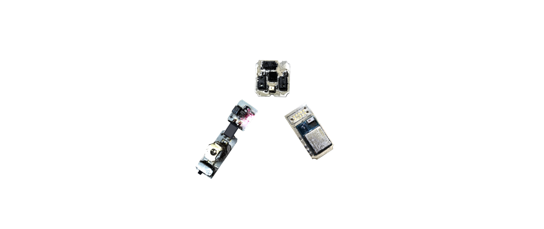
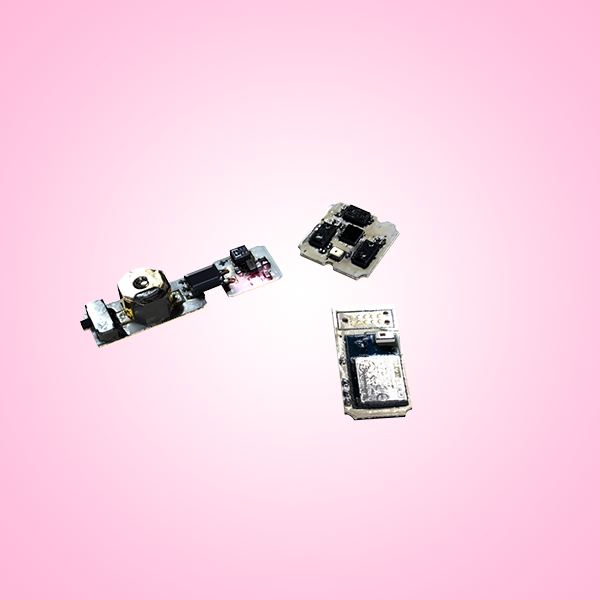
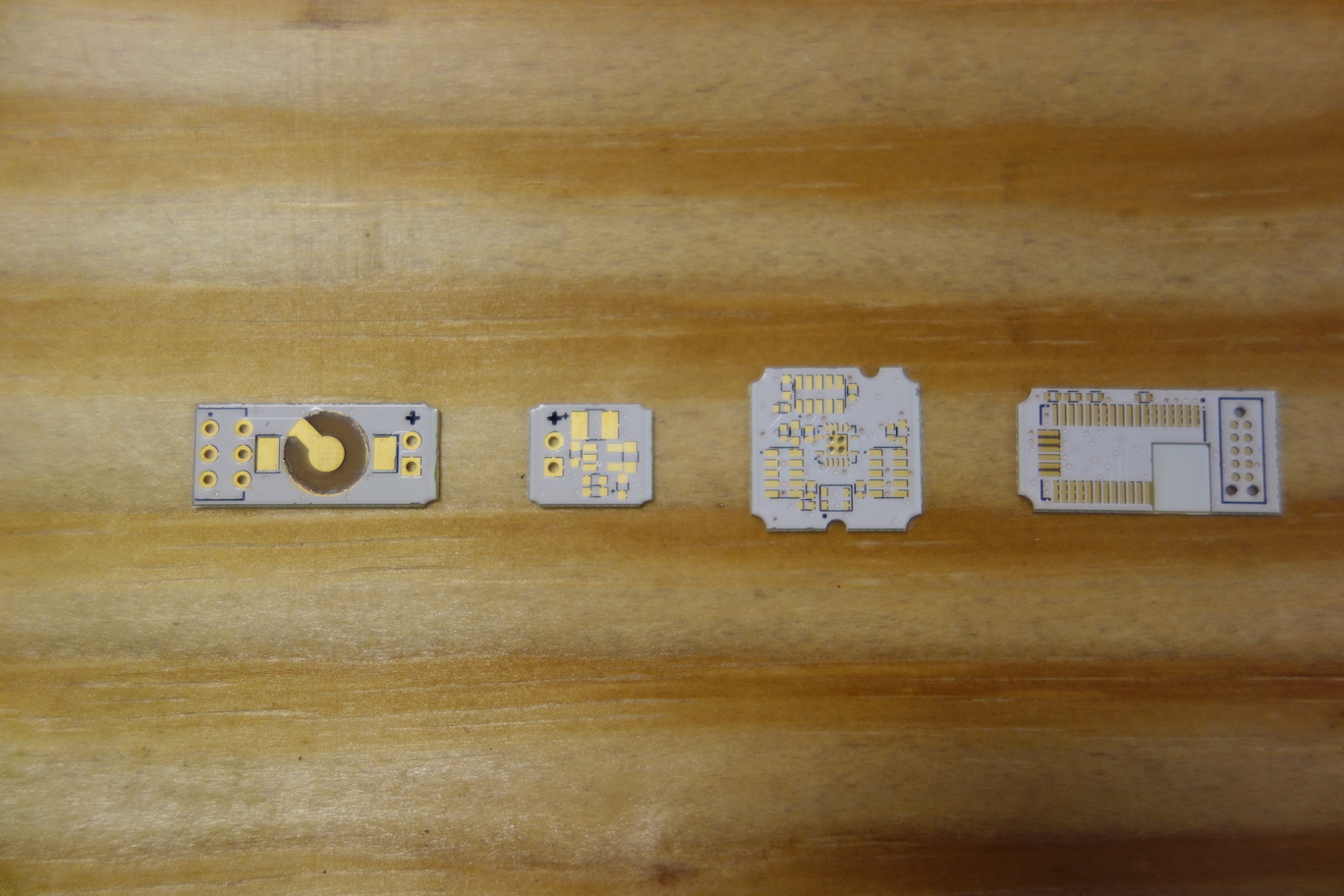
A complete Pallette circuitry consists of four boards (as shown in the photo below, from left to right): a Battery Board, a Voltage Regulator Board, a Sensor Board, and a Microcontroller Board.
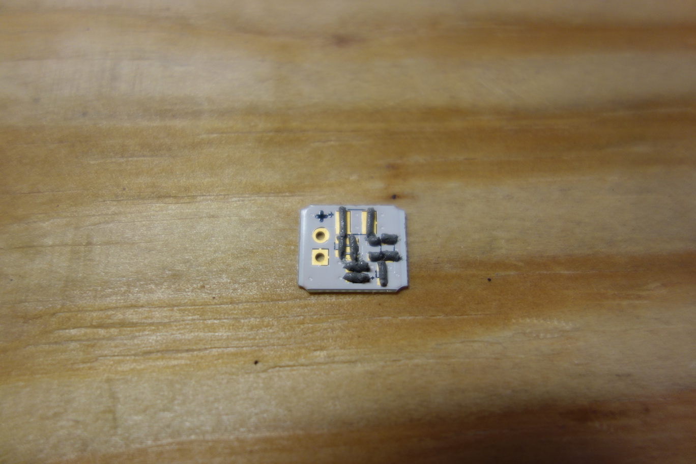
The photos below show you the process of reflow solder the Voltage Regulator Board.
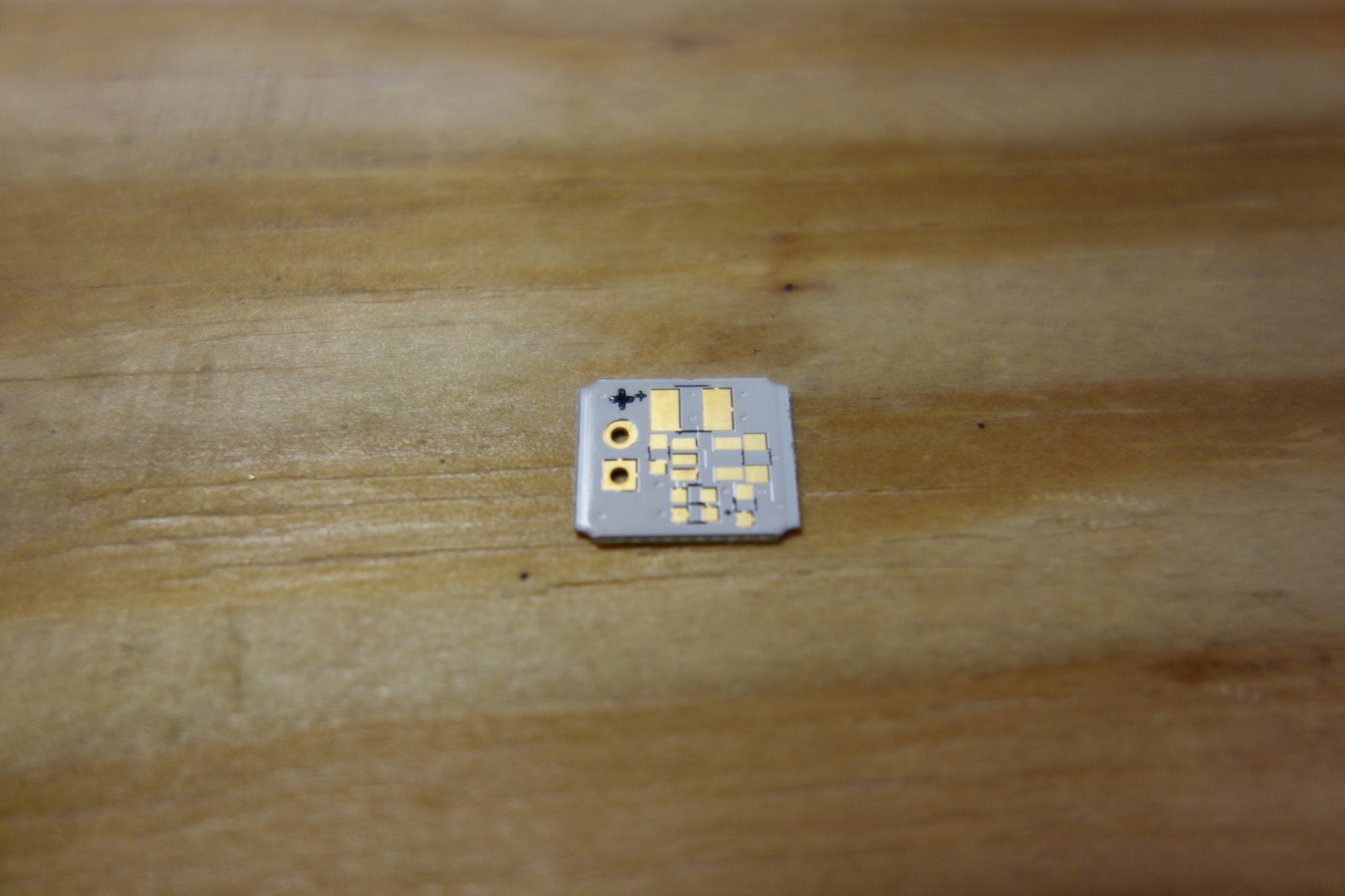
First apply solder paste on the solder pads.
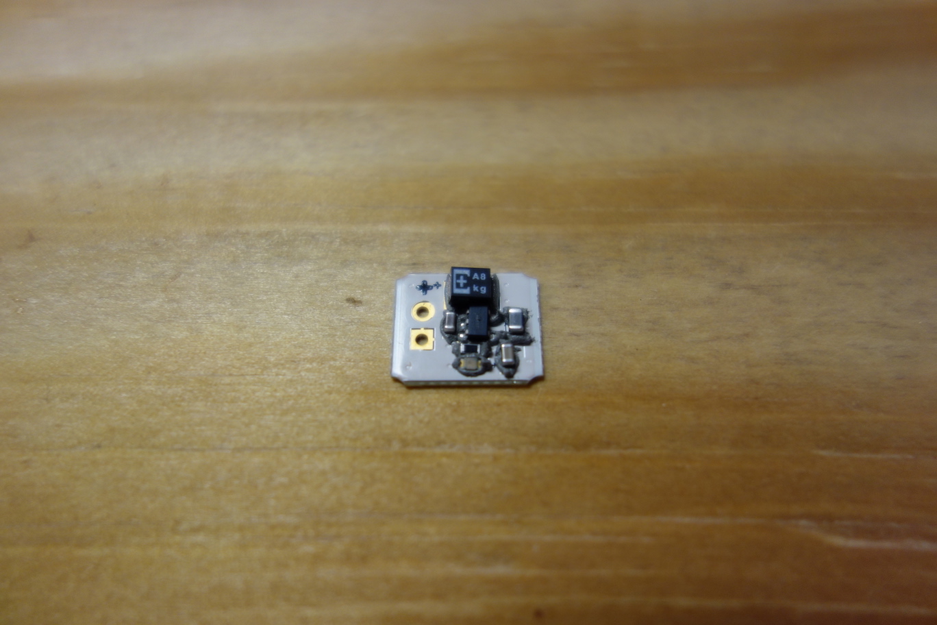
Next, place components on their designated locations. Make sure the polarities of the tantalum polymer capacitor and the LED are correct. The '+' symbol on one side of the footprint indicates anode.
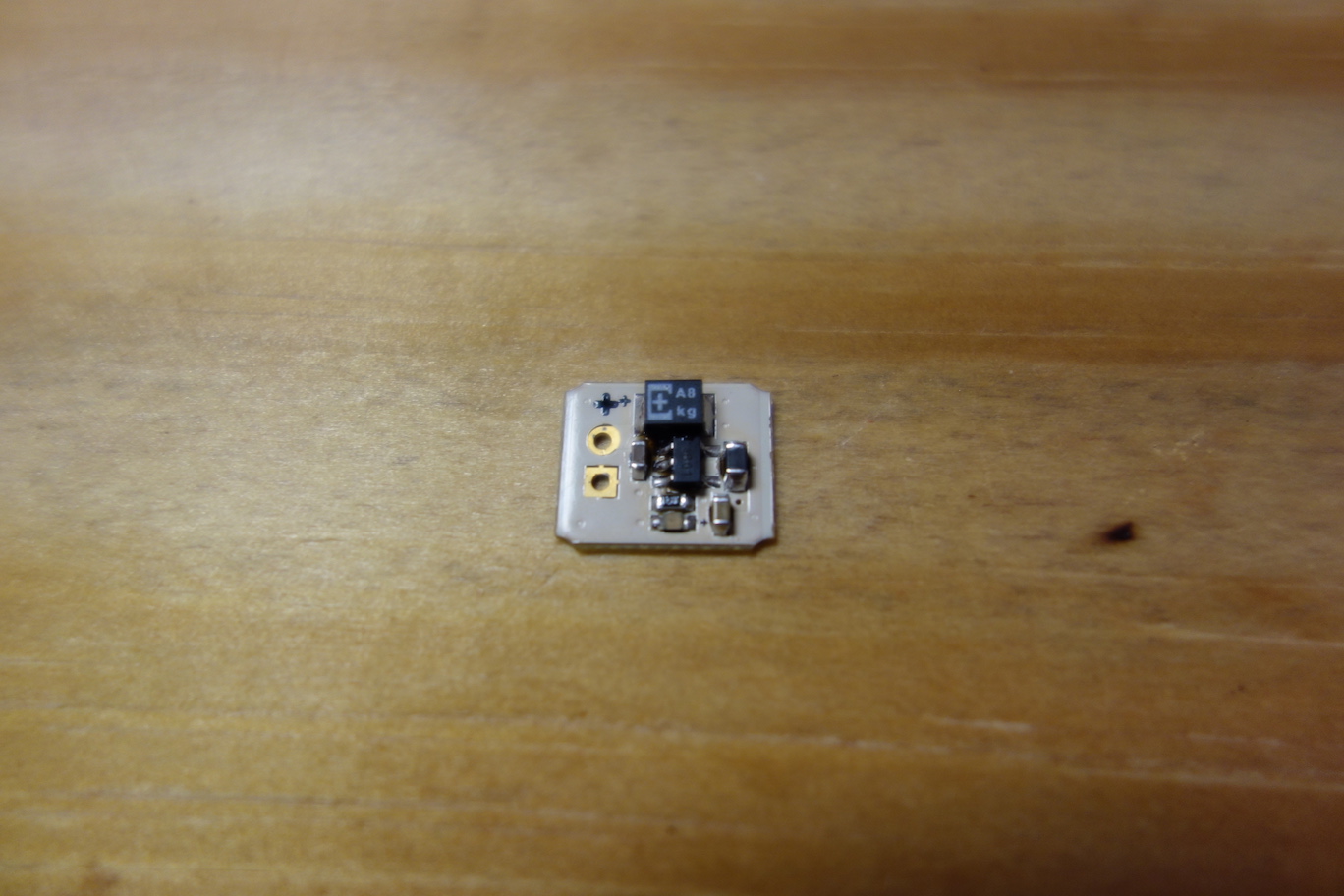
Turn on the hot plate, set the temperature to 210°C (410°F). When the temperature of the hotplate reaches 210°C, use tweezers to place the PCB to the center of the hotplate, wait until the solder paste melts completely (when the solder paste is shinning), then carefully remove the PCB from the hotplate using tweezers.
The video below lets you catch a glimpse of reflow soldering of the Pallette PCBs.
You can also watch the tutorial videos below to learn reflow soldering. For more resources, please go here.
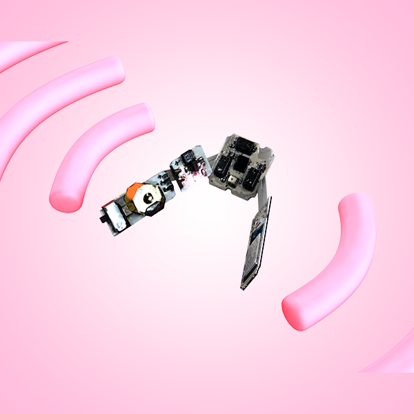
The component placement of the four boards is shown below.
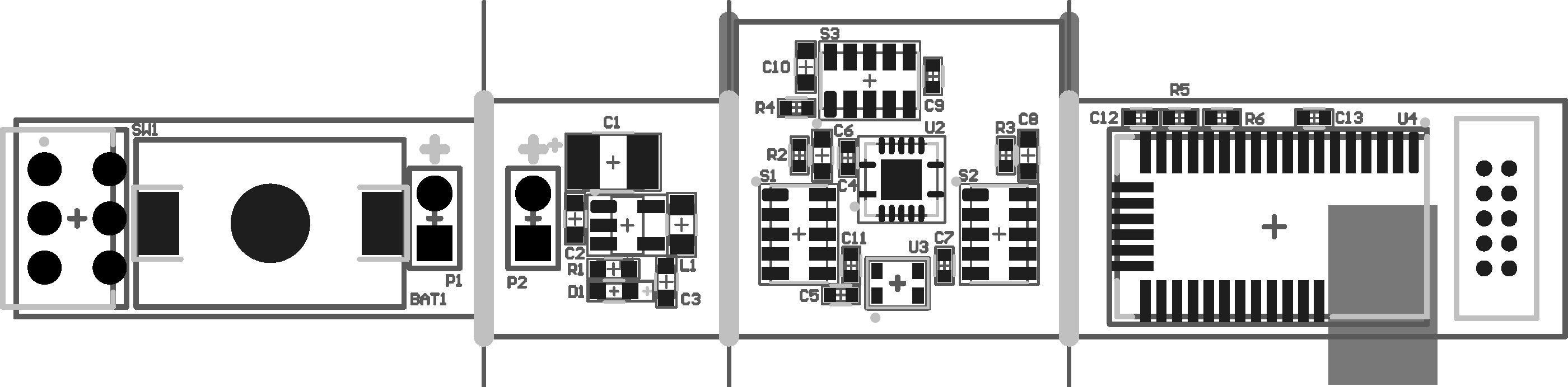
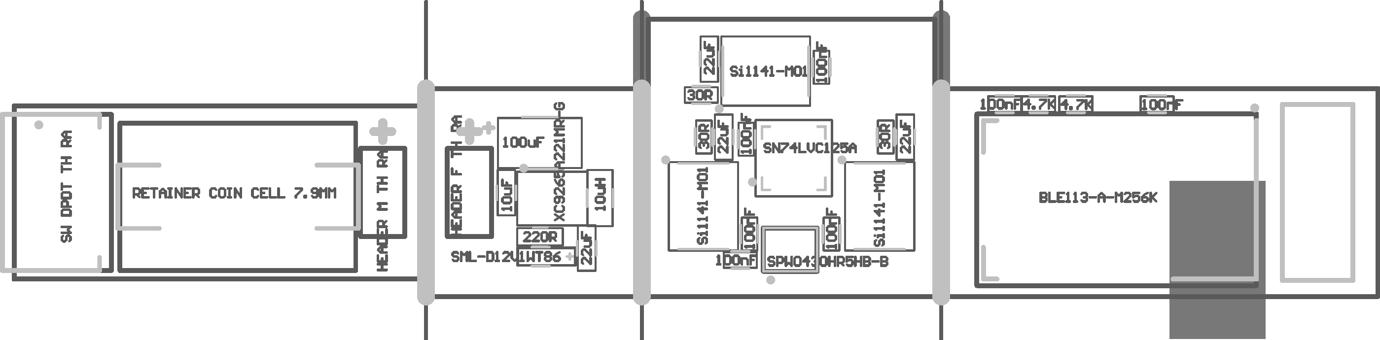
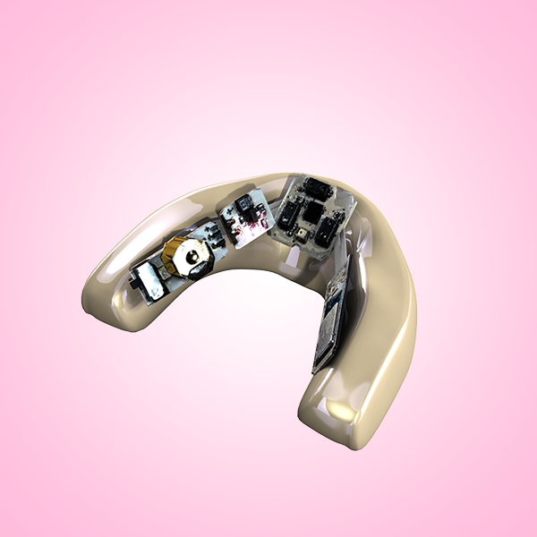
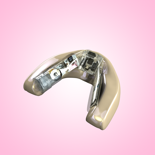
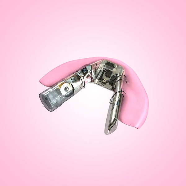
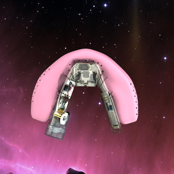
You can find more Pallette hardware schematics and drawings here. Once you finished soldering, your boards should look like this.
- The Battery Board
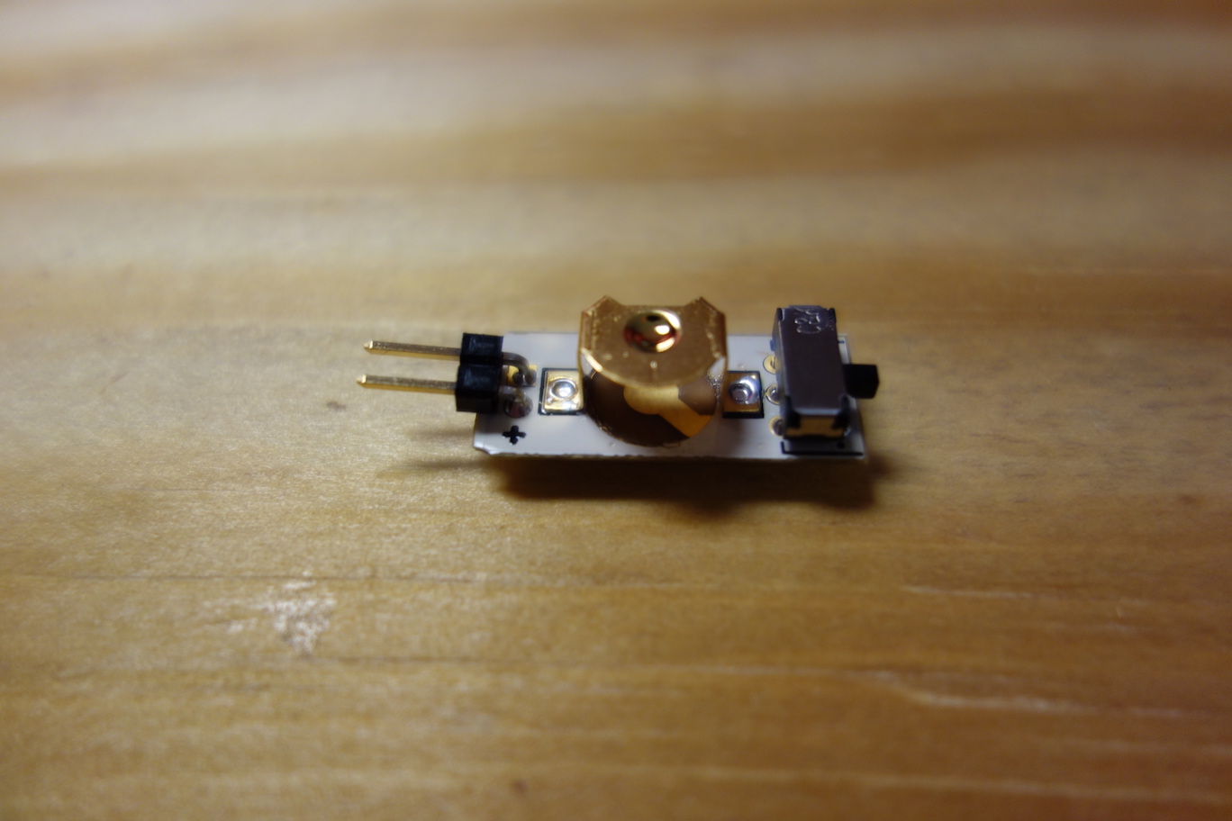
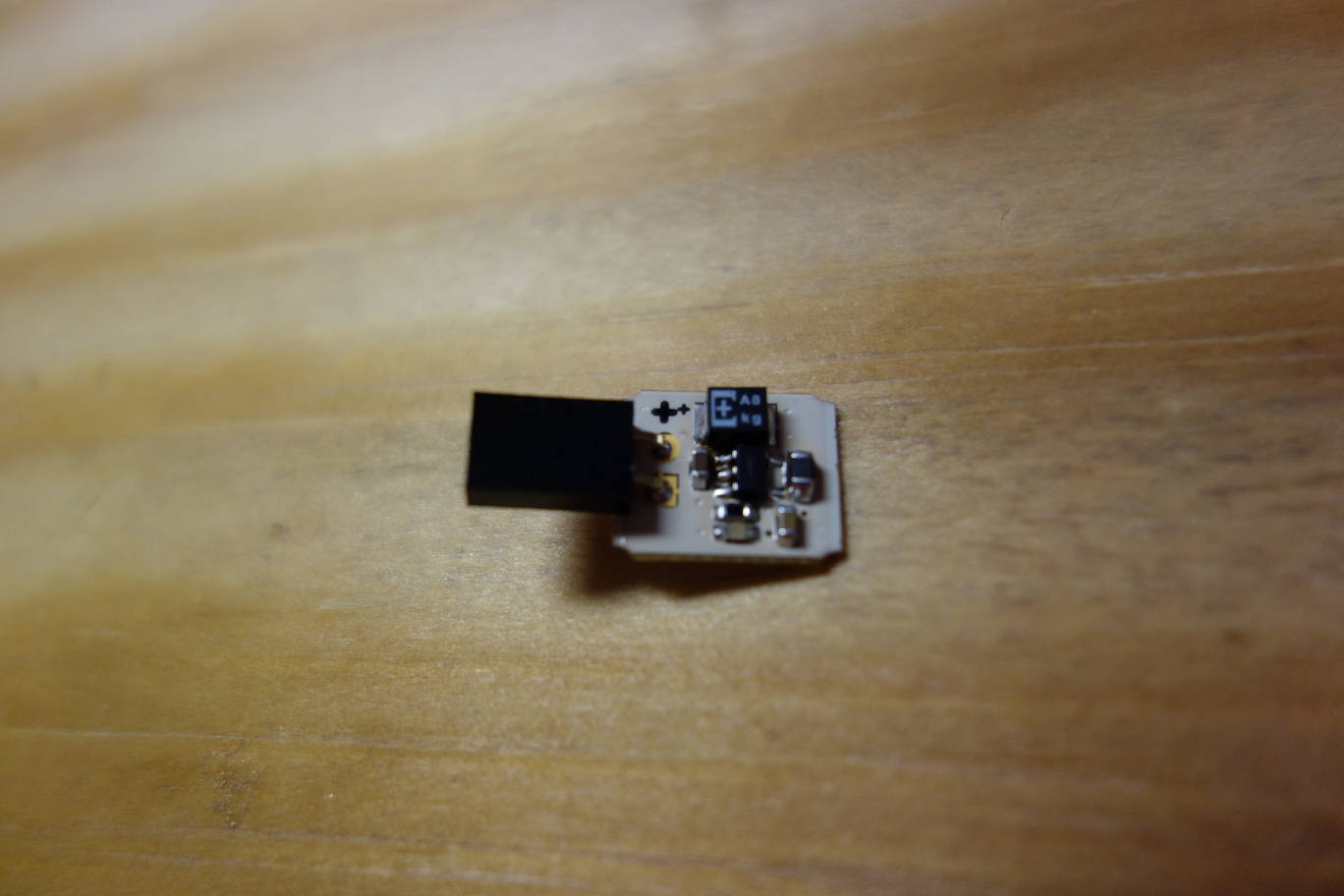
- The Voltage Regulator Board
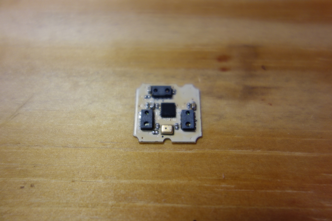
- The Sensor Board
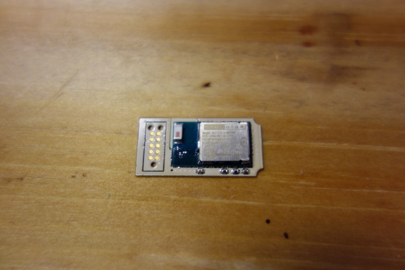
- The Microcontroller Board
Next, we will solder wires to the back of the boards to connect the boards together.